The parallel-out shift register is one of many ICs that can be used to multiplex one side of the matrix we are scanning. The basic concept is to save microcontroller pins by multiplexing the columns of your matrix. So, rather than just having the microcontroller activate a single column, data is clocked out through a shift register to activate the correct column. In this way, a very large number of columns can be addressed with only 2 or 3 microcontroller pins. An example of this is shown below.
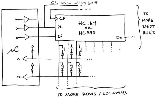
Figure 1 – Example parallel-out shift register mux schematic.
A parallel-out shift register takes the bit at its input, and moves it to the first output when a clock pulse is provided. With each clock pulse, all of the outputs are shifted over by one, until they finally exit. The 74HC164 or 74HC595, as well as others, can be used to perform this task. The ’164 is a little less expensive as it does not have output latches like the ’595. The output latches are not critical, and consume another microcontroller pin to operate. They allow you to present the data at the output of the shift register only after all the data has been clocked in. The ’595 is often used with LEDs, where a slight flicker might be seen if the data is clocked out slowly and not latched into place.
Of the 3 partially mux’d matrix options (parallel-in, parallel-out, and 3 to 8), the parallel-out has the most advantages. First off, it consumes the least microcontroller lines (2 in comparison to the other’s 3), and it can scale to many more switches using only those 2 lines. Secondly, it’s faster to read than the parallel-in version, as all 8 bits do not need to be serially clocked in for every column, as they do with the parallel-in shift register. Additionally, you need only clock the active line over to the next column with the parallel-out shift register, and then read all the mux rows in at once. The 3 to 8 can be slightly faster than this, but not by much.
Other advantages include the ability to have switches trigger interrupts. In fact, any switch can trigger an interrupt if you set all of the parallel-out lines active – an option not available with either of the two other methods. Finally, the data is easy to read on the input, and minimal code is required.
The only disadvantage of this method is that it requires an extra IC. But, this can not be avoided in some cases due to microcontroller pin limitations, and this is often the best alternative.