The more buttons and switches the better! There is no faster way to give input to your device than pushing a button dedicated to the task you want to do. Whether it’s an 88 key polyphonic keyboard, or a 256 button Monome, you’ll need to get all those data back into your microcontroller, where all the magic happens. There are a lot of different ways of doing this, and we will cover all of them, and show you the least expensive method for your setup. We even have an example of how a standard MIDI keyboard does it!
If you only have a few buttons, it’s a simple task to figure out what has been pressed. You simply connect a microcontroller pin to each button, and read in the level. But, what do you do when you have more switches than free pins? In this case, you must multiplex all those inputs. Multiplexing is the process of spreading out your task over more than one resource. So, if you don’t have enough free pins (your first resource), you need to take more time (your second resource) to get all the data in. Trading off time is one of the most common ways of multiplexing.
Here, we will be using ‘matrix scanning’ to do the multiplexing. This technique is used in computer keyboards and large LED displays. It involves setting up a grid (or matrix) of input lines. One set of these lines form columns, and the other rows. The ‘scanning’ occurs as you activate each column, one at a time, and read back the state of the switches which are connected to it. In this way, you use the same rows over and over again to check the level of many different switches. A schematic of this setup is shown below.
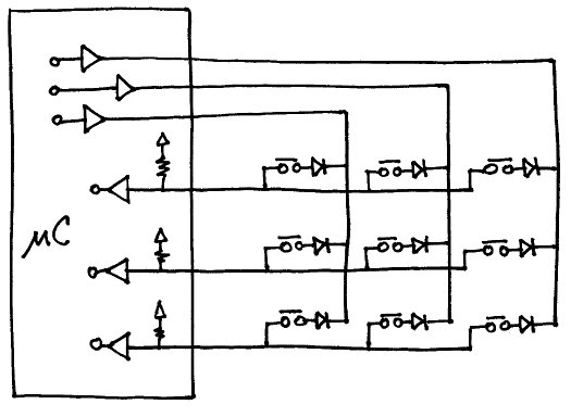
Figure 1. 3 x 3 switch matrix schematic.
There are 3 things to note in the matrix scanning example shown above. First, diodes are needed at each switch point. This is because all the switches are tied together via the scan lines. So even though a column may not be activated, switches on that column can still pull a line low or high by creating alternate pathways for the current to flow. The diodes prevent this by only allowing the current to flow one way. Second, you need resistors on the rows to pull them either high or low when no buttons are pressed. In fig. 1, the pull-up resistors shown are internal to the microcontroller. The final thing to note is that for each column you add, it will take that much longer to complete the scanning task. For example, if you have 4 columns, it will take at least 4 times as long to scan as it would without a matrix (i.e., the case of a single column). But it also allows you to use almost 1/4th the amount of input pins. And that is the fundamental trade-off with matrix scanning – input pins for time.
The following chart shows all possible combinations from 1 to 128 switches being multiplexed into anywhere from 1 to 20 microcontroller pins. Each box lists the least expensive alternative(s), and the colored regions are areas of similar cost. Note: This chart represents only those options that allow for true multi-touch – i.e. you can press any combination of buttons and it will work properly. For single button press options, things become considerably easier and cheaper. Cost is based on current (2011) prices at qty. 100.

Figure 2. Switch matrix scanning options sorted by cost. Click on the image to get a larger, readable version.
So, what are all those options above? Listed below are links to the various ways you can scan a matrix. An example of each method is shown, and the relative trade-offs are given. The three main trade-offs we will be looking at are cost, part count, and complexity. Complexity is a rather nebulous term which will try to capture the differences in how easy it is to implement a certain method. Some require considerably more code or specific hardware peripherals on your microcontroller.
Matrix Scanning Options:
A. Switch per pin
B. Single multiplexed
C. Subset of charliplexed
D. Shift register brigade
E. Parallel-out shift register mux’d with uC
F. Parallel-in shift register mux’d with uC
G. 3 to 8 decoder mux’d with uC
H. Latch mux’d with uC
I. Dual shift register mux
J. 3 to 8 decoder mux’d with shift register
K. Extra microcontroller
L. Serial I/O expander IC
*. Shift register hacks
*. XMEM matrix scanning
Another thing to consider when choosing a scanning option, is whether an interrupt line can be used. For some applications, timing is extremely critical, and the microcontroller must do an action exactly when the button is pressed and not some delayed time later when the scanning occurs. In these cases, you can use interrupt lines on the microcontroller which ‘interrupt’ what’s currently going on to deal with the incoming data. Shift registers generally preclude this from happening, as the data doesn’t directly connect to the microcontroller, and must be shifted in. The above examples also give information on the interrupt limitations of the various options.
The above chart is meant to serve as a starting point for designers. It covers the most common options, and shows where they are most applicable. If you find that you are on a borderline case, you may want to look at a few neighboring options to see which works best. If you want to dig a bit deeper, the full cost chart spreadsheet gives a starting point for getting exact pricing information.
— Footnote —
This tutorial was motivated by the fact, that when we put our engineering caps on, we often end up re-inventing the wheel. And although this can be amazingly fun and rewarding, at some point it really hinders the forward progress of our projects, and the state of the art in general. So the more we can document those things we’ve learned while solving our own little problems, the less someone else will have to do the same thing, and the more cool things there will be in the world.