Tools and Techniques for Musicians, Composers, and Tinkerers
spi and i2c
13 posts · 51301 views
by ajtaji » Wed Jan 29, 2014 12:53 UTC
I did a brief examination of the data sheet for this codec. I noticed it has a built in crystal but your shield uses an external? Why? Also the data sheet says the control lines are spi compatible but you wrote another routine to communicate with the arduino. What was the exact purpose of this? Why cant the standard spi library be set up to communicate with this chip. Finally you are using i2c also, I'm totally lost on this one? I bought this board, it came with no instruction manual, nor does the wiki explain why this was done over that, etc... back in the 80's you bought something it came with more information than you wanted, today is becoming a joke
by guest » Wed Jan 29, 2014 22:07 UTC
1. there is no internal oscillator/crystal on the codec.
2. the control lines are SPI compatible. but the SPI is used for the data lines, which are not SPI compatible, and needed to be hacked to work with the codec.
3. the I2C is used for the control ines.
the codec has 2 serial lines - control and data. the control sets up the parameters, and the data passes the audio information.
as someone who bought a lot of kits in the 80's, i would argue that you get way more information these days with DIY products. gerber files? eagle files? BOMs with manufacturer part numbers? forums to ask questions on? for the actual solder-it-yourself kits, most suppliers have detailed webpages with videos and pictures documenting each step. i remember getting a pcb, some parts, and a list of what went where. it would be helpful to include a list of design decisions with a finalized design, and some within the open hardware community have been trying to standardize ways of doing this, but for the designer it is quite time consuming to document why each component/trace/piece of code is was chosen. within the header files for a lot of code you will find some of this.
by ajtaji » Thu Jan 30, 2014 02:00 UTC
Thank you for that brief explanation...I knew there was a reason for it...now to dig more... I also bought sram and fpu which uses spi, thought there might have been some issue with spi itself
by guest » Thu Jan 30, 2014 12:46 UTC
which platform are you going to be using it with? some microcontrollers have 2 or more SPI lines. also, the UART on the arduino can be put into SPI mode (although this means no more USB). the SPI bus can also, IN THEORY, be multiplexed on the codec shield board, but i have never tried this. there is an enable line for the level translator.
by ajtaji » Sat Feb 01, 2014 01:53 UTC
Arduino Due and Uno, although the Uno I might have to breadboard the 328 and run it at 20mhz, I wont be doing anything for a while, lots of planning and research first, these are both new platforms for me...
by guest » Sun Feb 02, 2014 00:04 UTC
ok, the due came out after we designed the codecshield, so it does not work out of the box with it. the SPI hack needs to be rewritten for the due, although the due probably has i2s on it, and that would be preferable to use.
by liner » Wed Apr 30, 2014 16:39 UTC
I am currently using the Audio codec shield with an Arduino UNO without problems but I would like to use the Arduino to control another device that also uses SPI. I am afraid there might be some conflict between the two devices. Could you give some explanation on how to do this? Thank you.
by guest » Wed Apr 30, 2014 18:53 UTC
there is a buffer between the spi out on the uno, and the spi in on the codec. so in theory, the lines can be disengaged, and the data sent elsewhere. but, the codec needs to recieve its spi data at very precise intervals (within 250ns!) so the other device can not block it. if its an SD card, it will be really difficult to set it up so its non-blocking. what is the other device?
by liner » Wed May 14, 2014 13:06 UTC
Hi,
Thank you for your answer. I ended up using another digital pin for the other device and setting the same clock on both devices. It seems to be working.
by guest » Wed May 14, 2014 23:11 UTC
glad to hear its working. if youre using the same clock for both SPI devices, how are you changing the data on the data line for the other one?
by jayache80 » Tue Apr 14, 2015 04:37 UTC
Hello. I am also curious about the oscillator- the datasheet for the WM8731 seems to strongly suggest there is an internal oscillator. It says "A crystal oscillator is included on board the device" and it is pictured on the block diagram, lower left.
Attachments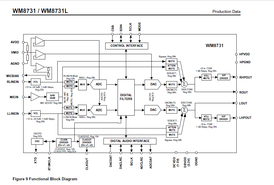
by guest » Tue Apr 14, 2015 13:55 UTC
the OSC they show in the diagram is just the driver circuit, not the crystal itself. you need to add a crystal to make it work, or send it a square wave from another source.
by jayache80 » Thu Apr 16, 2015 06:00 UTC
Thank you. I was confusing myself. For anyone else:
It says "For applications where it is desirable that the WM8731/L is the system clock source, then clock
generation is achieved through the use of a suitable crystal connected between the XTI/MCLK input
and XTO output pins"
which can be interpreted as: "The Wolfson chip can be the master clock if you connect a crystal to it. It has its own on-board circuitry to generate the clock based on that crystal's output"
And goes on to say "For applications where a component other than the WM8731/L will generate the reference clock, the external system can be applied directly through the XTI/MCLK input pin with no software
configuration necessary. Note that in this situation, the oscillator circuit of the WM8731/L can be
safely powered down to conserve power"
which can be interpreted as "If you have another device being the master clock, just feed that clock to the same place you would put the crystal. You don't even need the on-board clock generation circuitry anymore so you can turn it off to save power"
Thanks again.