Board index › Products › Audio Codec Shield

DAC in Audio Codec Shield

23 posts · 73025 views

DAC in Audio Codec Shield

by liner » Fri Jun 29, 2012 09:13 UTC
Hi all,

I just want to use the DAC in the Audio Codec Shield in a way that the Arduino uno sets a digital number and we can get an analogue output.

Any approaches of how to start?

Thankx

Re: DAC in Audio Codec Shield

by guest » Fri Jun 29, 2012 16:39 UTC
that should be pretty easy
but be sure to take your output
from the line_out solder pads
and not the headphone

the headphone output is only AC voltages

in all of the examples there is a line like this
AudioCodec_data(&left_in, &right_in, left_out, right_out);
you write your value to left_out or right_out
depending upon where you have the wire connected

Re: DAC in Audio Codec Shield

by liner » Thu Jul 05, 2012 08:48 UTC
Thank you, guest.

Just what I needed. It is quite simple in fact, I just did not understand well that function.

Re: DAC in Audio Codec Shield

by vickyjungade » Tue Sep 18, 2012 10:35 UTC
What is acceptable value (range or discrete) as an argument to the function AudioCodec_data for giving out a voltage say 3.5V or 5V? I tried passing different values for left_out as well as right_out - 125, 500 or 32767. But none of these could give me any analog out (DAC out was zero).

I tried sine_generator sketch from the examples and could see sine wave on a scope (HP_Out); adjustable freq & amplitude with the mods - so nothing wrong with the hardware setup.

Inside sine_generator -
I am not able to understand the co-relation between values in the look up table (sinetable.inc) & the generated wave.
I would also like to know how pgm_read_word_near function works?
The Arduino IDE does not show this function in orange color like others. How is that???
I tried passing values from the lookup directly to this function, but that does not work as well.

Re: DAC in Audio Codec Shield

by guest » Tue Sep 18, 2012 18:15 UTC
the headphone out is AC
so if you want a DC voltage that doesnt change with time
you will need to use the line_out pads

the DAC goes to 3.3v
and this is at 0x7fff = 32767

program_read_word_near() is a C function for reading values from internal flash program memory. there isnt an arduino command to do this. all it does, is fetch a value that has been stored into the program memory, at a location specified by the value that you give to the function. if you take these values and send them to left_out and right_out, they will appear at the output.

the values are signed integers, so 0x8000 = -32768 = 0v. 0x0000 = 0 = 1.65v. 0x7fff = +32767 = 3.3v. if you want to convert between signed and unsigned you can do this:
unsigned int i = 0; // declare variable
signed int j = 0; // declare variable
i = j + 0x8000; // i is now an unsigned version of j
j = i + 0x8000; // j is now a signed version of i


note that its the same code to go from signed to unsigend, and from unsigned to signed.

Re: DAC in Audio Codec Shield

by vickyjungade » Sat Sep 22, 2012 09:43 UTC
Ok, so we tried to substitute the call to DAC as AudioCodec_data(&left_in, &right_in, 58773, 58773); or AudioCodec_data(&left_in, &right_in, 0x7fff, 0x7fff);

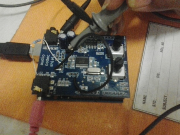
& tried to read with a scope from the pad labelled OUT from its R & L. see attachment.

Yet we are not getting any voltage.

suppose we try the original sine wave program, we can read sine wave as before.

please help me out!


see we modified only 1 line:
/*
sine_generator.pde
guest openmusiclabs 7.7.11
this program creates a sinewave of variable frequency and
amplitude, presented at both left and right outputs. there
isnt any interpolation, so you only get 256 discrete frequencies
across the span of 44Hz to 10kHz.
*/

// setup codec parameters
// must be done before #includes
// see readme file in libraries folder for explanations
#define SAMPLE_RATE 44 // 44.1kHz sample rate
#define ADCS 2 // use both ADCs

// include necessary libraries
#include <Wire.h>
#include <SPI.h>
#include <AudioCodec.h>

// create data variables for audio transfer
// even though there is no input needed, the codec requires stereo data
int left_in = 0; // in from codec (LINE_IN)
int right_in = 0;
int left_out = 0; // out to codec (HP_OUT)
int right_out = 0;

// create variables for ADC results
// it only has positive values -> unsigned
unsigned int mod0_value = 0;
unsigned int mod1_value = 0;

// create sinewave lookup table
// PROGMEM stores the values in the program memory
// it is automatically included with AudioCodec.h
PROGMEM  prog_int16_t sinewave[]  = {
  // this file is stored in AudioCodec.h and is a 1024 value
  // sinewave lookup table of signed 16bit integers
  // you can replace it with your own waveform if you like
  #include <sinetable.inc>
};
unsigned int location; // lookup table value location


void setup() {
  // call this last if you are setting up other things
  AudioCodec_init(); // setup codec and microcontroller registers
}

void loop() {
  while (1); // reduces clock jitter
}

// timer1 interrupt routine - all data processed here
ISR(TIMER1_COMPA_vect, ISR_NAKED) { // dont store any registers

  // &'s are necessary on data_in variables
  AudioCodec_data(&left_in, &right_in, 58773, 58773);
  
  // create some temporary variables
  // these tend to work faster than using the main data variables
  // as they arent fetched and stored all the time
  int temp1;
  int temp2;
  
  // create a variable frequency and amplitude sinewave
  // fetch a sample from the lookup table
  temp1 = pgm_read_word_near(sinewave + location);
  // step through table at rate determined by mod1
  // use upper byte of mod1 value to set the rate
  // and have an offset of 1 so there is always an increment.
  location += 1 + (mod1_value >> 8);
  // if weve gone over the table boundary -> loop back
  // around to the other side.
  location &= 0x03ff; // fast way of doing rollover for 2^n numbers
                      // otherwise it would look like this:
                      // if (location >= 1024) {
                      // location -= 1024;
                      // }
  
  // set amplitude with mod0
  // multiply our sinewave by the mod0 value
  MultiSU16X16toH16(temp2, temp1, mod0_value);
  // our sinewave is now in temp2
  left_out = temp2; // put sinusoid out on left channel
  right_out = -temp2; // put inverted version out on right chanel

  // get ADC values
  // & is required before adc variables
  AudioCodec_ADC(&mod0_value, &mod1_value);

  reti(); // dont forget to return from the interrupt
}
Attachments
2012-09-22 15.05.58.jpg

Re: DAC in Audio Codec Shield

by guest » Sat Sep 22, 2012 18:15 UTC
heres how you can use the codecshield dac

/*
dac_out_using_main.pde
guest openmusiclabs 9.22.12
this program allows the user to update the dac output in the main loop.
it also allows the user to use unsigned values.  but, it does not update
the sample at every sample period, so it may not work well for playing
back wavetables or other synchronous data.
*/


// setup codec parameters
// must be done before #includes
// see readme file in libraries folder for explanations
#define SAMPLE_RATE 44 // 44.1Khz
#define ADCS 0 // no ADCs are being used

// include necessary libraries
#include <Wire.h>
#include <SPI.h>
#include <AudioCodec.h>

// create data variables for audio transfer
int left_in = 0x0000;
int left_out = 0x0000;
int right_in = 0x0000;
int right_out = 0x0000;

void setup() {
  AudioCodec_init(); // setup codec registers
  // call this last if setting up other parts
}

void loop() {
  unisgned int i; // do whatever calculating you want 
  left_out = i +  0x8000; // convert to signed value
}

// timer1 interrupt routine
ISR(TIMER1_COMPA_vect) { 
  // &'s are necessary on data_in variables
  AudioCodec_data(&left_in, &right_in, left_out, right_out);  
}


AudioCodec_data() can only take variables, not constant numbers.

Re: DAC in Audio Codec Shield

by guest » Sat Sep 22, 2012 19:28 UTC
also
if you want to tell me a bit more about what youre doing
i might be able to help more

Re: DAC in Audio Codec Shield

by vickyjungade » Sun Sep 23, 2012 07:04 UTC
We could write through the DAC properly. Thanks!

We are implementing a PID as described in http://en.wikipedia.org/wiki/PID_controller. Any suggestions?

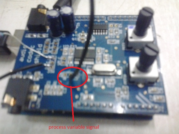
The ADC is to read the process variable, DAC is to transmit the control value.

Please explain how to:

0. Read the ADC properly. Which pin to connect the process variable signal? We could not correctly read a DC voltage (or sine) through function AudioCodec_data, (argument &left_in or &right_in) when connected to IN as shown in attachment.
1. set the interval of the ISR that calls the read & write functions, as we have to write our functionality in loop()
2. use the 24 bit ADC & 32 bit DAC for accuracy. Please explain how to? What is the 'maximum resulution' of ADC & DAC that can be used , i mean 16 bit or 18 bit or 24 bit. We need a ADC/DAC with max code width, hence this card!
1. the range for left_in & right_in is -32768 to 32767. Also the range for left_out & right_out is the same. Besides the defination of AudioCodec_data shows that these parameters are int. Why so?
2. the AudioCodec_readme.txt says, for the function AudioCodec_ADC - "the ADC is only a 10bit ADC". Why so?
3. Also, how to read & write, ADC & DAC by calls in loop function without using interrupt
Attachments
2012-09-23 16.30.56.jpg

Re: DAC in Audio Codec Shield

by guest » Sun Sep 23, 2012 19:40 UTC
a PID controller sounds awesome

for that you will want to do all the processing in the ISR. it is important that the data gets processed in a synchronous fashion, and you could do it in the main loop, but it is easier and faster to do it in the ISR. here is some code that can get you started. your input signal will need to go from 0v to 3.3v.

/*
dc_controller.pde
guest openmusiclabs 9.23.12
this takes in a dc value from the codecshield, processes it, and
sends out a dc value on the codecshield. 
*/


// setup codec parameters
// must be done before #includes
// see readme file in libraries folder for explanations
#define SAMPLE_RATE 44 // 44.1Khz
#define ADCS 0 // no ADCs are being used
#define ADCHPD 1 // set the codecshield to DC input

// include necessary libraries
#include <Wire.h>
#include <SPI.h>
#include <AudioCodec.h>

// create data variables for audio transfer
int left_in = 0x0000;
int left_out = 0x0000;
int right_in = 0x0000;
int right_out = 0x0000;
int last_value = 0;
int difference = 0;
int integral = 0;
int position = 0;

void setup() {
  AudioCodec_init(); // setup codec registers
  // call this last if setting up other parts
}

void loop() {
  while (1); // reduces clock jitter
}

// timer1 interrupt routine - all data processed here
ISR(TIMER1_COMPA_vect, ISR_NAKED) { // dont store any registers

  // &'s are necessary on data_in variables
  AudioCodec_data(&left_in, &right_in, left_out, right_out);
  
  difference = left_in - last_value; // create a difference signal
  position = left_in; // create a position signal
  integral +=  left_in; // create an integral signal
  last_value = left_in; // backup the last value
  // do the math here for pid
  
  // dont forget to return from interrupt
  reti();
}

Re: DAC in Audio Codec Shield

by guest » Sun Sep 23, 2012 19:57 UTC
answers to your points above:

0. in needs to go to L_IN, at the solder pad, which is what it looks like you have. this bypasses the analog high-pass filter. you also need to set ADCHPD 1 in the code, which the example above does. this shuts off the digital high-pass filter on the codec.

1. with the code above, you no longer use loop(), so this shouldnt be a problem. the ISR is called automatically, at a rate set by SAMPLE_RATE. i would reccomend setting SAMPLE_RATE to the lowest value you can get away with. this will give you maximum processing time.

2. the codec on the shield can theoretically go to 24bit, but the noise level in the codec isnt much better than 16b, and your signal will probably not be any better than that as well, so to go to 24b would just make things more complicated for very little gain. also, the codecshield library isnt setup to handle 24b numbers. so some new functions would need to be written.

1. the values are int because they are 16b signed numbers coming out of the codec. that is how the codec produces the data

2. the ADC that is being referred to in the read_me is on the arduino, not the codec. so the arduino ADC is limited to 10b, but the codec ADC is 16b.

3. i would reccomend using the interrupt, as it will keep the timing better, give more processing time, and you wont have to worry if your variables are getting clobbered during the interrupt. the interrupt is required for the codec to operate. if you need to do some things in the main loop, let me know, and i can help with that. it is a bit complicated, as you need to declare some variables volatile, and then disable interrupts while certain variables are being altered. its a bit of a pain, and should be avoided.

Re: DAC in Audio Codec Shield

by vickyjungade » Wed Sep 26, 2012 13:24 UTC
So we tried the library for PID by Brett Beauregard available at http://www.arduino.cc/playground/Code/PIDLibrary

Here's the code:

/*
dc_controller.pde
guest openmusiclabs 9.23.12
this takes in a dc value from the codecshield, processes it, and
sends out a dc value on the codecshield. 
*/


// setup codec parameters
// must be done before #includes
// see readme file in libraries folder for explanations
#define SAMPLE_RATE 88 // 44.1Khz
#define ADCS 0 // no ADCs are being used
#define ADCHPD 1 // set the codecshield to DC input

// include necessary libraries
#include <Wire.h>
#include <SPI.h>
#include <AudioCodec.h>

// create data variables for audio transfer
int left_in = 0x0000;
int left_out = 0x0000;
int right_in = 0x0000;
int right_out = 0x0000;
int last_value = 0;
int difference = 0;
int integral = 0;
int position = 0;

// so much for audio codec

// now for PID
/********************************************************
 * PID Basic Example
 ********************************************************/

#include <PID_v1.h>

//Define Variables we'll be connecting to
double Setpoint, Input, Output;

//Specify the links and initial tuning parameters
PID myPID(&Input, &Output, &Setpoint,2,5,1, DIRECT);
// so much for PID

// Program variables
boolean flip = true;

void setup() {
  AudioCodec_init(); // setup codec registers
  // call this last if setting up other parts
  Serial.begin(9600);
  
  Setpoint = 12000;
  
    //turn the PID on
  myPID.SetMode(AUTOMATIC);
  
  pinMode(2, OUTPUT); 
}

void loop() {
  while (1); // reduces clock jitter
 /*
  Serial.print("Input = " );                       
  Serial.print(left_in);      
  Serial.print("\t Output = ");      
  Serial.println(left_out);
  delay(3000);
  */
}

// timer1 interrupt routine - all data processed here
ISR(TIMER1_COMPA_vect, ISR_NAKED) { // dont store any registers
   
  // &'s are necessary on data_in variables
  
  AudioCodec_data(&left_in, &right_in, left_out, right_out);
  
  difference = left_in - last_value; // create a difference signal
  position = left_in; // create a position signal
  integral +=  left_in; // create an integral signal
  last_value = left_in; // backup the last value
  // do the math here for pid
  Input = -left_in;
  myPID.Compute();
  left_out = Output; 
  flip = !flip;
  digitalWrite(2, flip); 
  
  
  // dont forget to return from interrupt
  reti();
}

To use the code above you have to place PID_v1 folder (from the url above) into the Arduino\Libraries directory

We flipped a digital out every time we run our code to read/write and compute as above in the ISR.
What we discovered on pin 2 is that we get a frequency of 14KHz only! If we comment the whole code in ISR so that the only thing the ISR does is flip the DO, then we get a frequency of 43.86KHz

We wish to have better PID bandwidth (PID bandwidth is the rate at which you can correct the control value once you read the process variable). Right now it is 14KHz, how to improve it? Changes to #define SAMPLE_RATE 88 // 44.1Khz does not make any difference.

Is there anyway you can do it? We have to change the PID later to include more complex algorithm, so faster the merrier!

Re: DAC in Audio Codec Shield

by guest » Wed Sep 26, 2012 16:52 UTC
digitalwrite() takes a really long time.

in setup() put this line:
DDRD |= 0x4; // sets pin2 to output

then replace digitalwrite with:
PORTD = (PORTD & 0x04) ^ PORTD; // toggles pin2

Re: DAC in Audio Codec Shield

by vickyjungade » Mon Oct 01, 2012 15:44 UTC
Hey thanks so far.

We have combined Audio Codec & PID & are facing an issue.

Whenever we run the code the output is calculated as 0 no matter what!

However, if we comment out Audiocodecinit() (in void setup) & Audiocodecdata() (in ISR) then our pid calculates output values correctly i.e. it starts from 0 and increases till max output limits (we've given hardcoded input value for experimenting)

If we uncomment Audiocodecinit() (in void setup) & Audiocodecdata() (in ISR) then our pid calculates wrong output values i.e. output value = 0

/*
dc_controller.pde
guest openmusiclabs 9.23.12
this takes in a dc value from the codecshield, processes it, and
sends out a dc value on the codecshield. 
*/

// setup codec parameters
// must be done before #includes
// see readme file in libraries folder for explanations
#define SAMPLE_RATE 88 // 44.1Khz
#define ADCS 2 // no ADCs are being used
#define ADCHPD 1 // set the codecshield to DC input

// include necessary libraries
#include <Wire.h>
#include <SPI.h>
#include <AudioCodec.h>

// create data variables for audio transfer
int left_in;// = 0x0000;
int left_out;// = 0x0000;
int right_in;// = 0x0000;
int right_out;// = 0x0000;

//TEMP Serial Buffer
String SerialBuffer, temp;
char *buffer;
char TempSerial[39];
int si;

// so much for audio codec

// now for PID


#include <PID_v1.h>

//Define the aggressive and conservative Tuning Parameters
double aggKp=4, aggKi=0.2, aggKd=1;
double consKp=2, consKi=5, consKd=1;
double gap;
double Setpoint, Input, Output, Temp = 0.0;


//Specify the links and initial tuning parameters
//PID myPID(&Input, &Output, &Setpoint, consKp, consKi, consKd, DIRECT);
PID myPID(&Input, &Output, &Setpoint,2,5,1, DIRECT);


void setup() {
  Serial.begin(115200); 
  AudioCodec_init();
  Setpoint = 50000;
  myPID.SetMode(AUTOMATIC);
  //myPID.SetSampleTime(1000);
  myPID.SetOutputLimits(0, 65535);
  //myPID.SetTunings(consKp, consKi, consKd);
}

void loop() {
  //Input = 32768 + left_in;
  Input = 45000; //32768 - left_in;

  //Input = 5.0; //left_in;
  myPID.Compute();
  Serial.println(Output);
  /*
  left_out = Output; 
  if(Serial.available() > 38) {
    for(si=0; si<40; si++){
      TempSerial[si] = Serial.read();
    }
    
    Serial.flush();    
    SerialBuffer = TempSerial;
    
      if (SerialBuffer.startsWith("START ") || SerialBuffer.endsWith(" END")) {
        temp = SerialBuffer.substring(6,9);
        buffer = &temp[0];
        consKi = strtod (buffer, NULL);
        temp = SerialBuffer.substring(10,13);
        buffer = &temp[0];
        consKp = strtod (buffer, NULL);
        temp = SerialBuffer.substring(14,17);
        buffer = &temp[0];
        consKd = strtod (buffer, NULL);
        temp = SerialBuffer.substring(18,21);
        buffer = &temp[0];
        aggKi = strtod (buffer, NULL);
        temp = SerialBuffer.substring(22,25);
        buffer = &temp[0];
        aggKp = strtod (buffer, NULL);
        temp = SerialBuffer.substring(26,29);
        buffer = &temp[0];
        aggKd = strtod (buffer, NULL);
        temp = SerialBuffer.substring(30,35);
        buffer = &temp[0];
        Setpoint = strtod (buffer, NULL);
        Serial.println("OUTPUT");
     }
      else {
        Serial.println("Err1");
      }

  }

  /*
  gap = abs(Setpoint-Input); //distance away from setpoint
  
  if(gap<10)
  {  //we're close to setpoint, use conservative tuning parameters
    myPID.SetTunings(consKp, consKi, consKd);
  }
  else
  {
     //we're far from setpoint, use aggressive tuning parameters
     myPID.SetTunings(aggKp, aggKi, aggKd);
  }

 //AudioCodec_data(&left_in, &right_in, left_out, right_out);
 Serial.print("Input   : ");
 Serial.print(Input);
 Serial.print(" Output   : ");
 Serial.println(Output);
 delay(300); 
     */
}

ISR(TIMER1_COMPA_vect) {
  //AudioCodec_data(&left_in, &right_in, left_out, right_out);
  //Input = left_in*3.3/32767;
  //myPID.Compute();
  //left_out = Output; 

}


Any thoughts why?
Re: DAC in Audio Codec Shield

by guest » Mon Oct 01, 2012 19:06 UTC
audiocodec_init() kills the delay timer. the codec needs to be run at a very consistent timing interval, or it stops sending data, and the delay timer messes with this. so you cant use delay(). this is also why audiocodec_data() needs to be in the ISR. another thing, is that variables altered in the ISR need to be declared as "volatile", otherwise the compiler doesnt know its being changed. this is probably the main thing thats causing trouble.

Re: DAC in Audio Codec Shield

by vickyjungade » Wed Oct 03, 2012 06:17 UTC
Consider this code:

#define SAMPLE_RATE 88
#define ADCS 2
#define ADCHPD 1
#include <Wire.h>
#include <SPI.h>
#include <AudioCodec.h>
#include <PID_v1.h>
int left_in;
int left_out;
int right_in;
int right_out;
double Setpoint, Input, Output, Temp = 0.0;
PID myPID(&Input, &Output, &Setpoint,2,5,1, DIRECT);

void setup() {
  Serial.begin(115200); 
  AudioCodec_init();
  Setpoint = 50000;
  myPID.SetMode(AUTOMATIC);
  myPID.SetOutputLimits(0, 65535);
}

void loop() {
  Input = 45000;
  myPID.Compute();
  Serial.println(Output);
}

ISR(TIMER1_COMPA_vect) {
}


Still the output is given as zero as the line AudioCodec_init(); is present in setup. Commenting this line solves the problem.

May we request your big help in this?

Re: DAC in Audio Codec Shield

by guest » Wed Oct 03, 2012 21:40 UTC
the PID library uses the millis() counter, which requires timer0 interrupt, which audiocodec_init() disables. to re-enable the interrupt, type the following after audiocodec_init():

TIMSK0 = 0x01;

i read through the PID library, and i dont think it will be able to execute very fast. this is the code from the header file:

void PID::Compute()
{
   if(!inAuto) return;
   unsigned long now = millis();
   unsigned long timeChange = (now - lastTime);
   if(timeChange>=SampleTime)
   {
      /*Compute all the working error variables*/
	  double input = *myInput;
      double error = *mySetpoint - input;
      ITerm+= (ki * error);
      if(ITerm > outMax) ITerm= outMax;
      else if(ITerm < outMin) ITerm= outMin;
      double dInput = (input - lastInput);
 
      /*Compute PID Output*/
      double output = kp * error + ITerm- kd * dInput;
      
	  if(output > outMax) output = outMax;
      else if(output < outMin) output = outMin;
	  *myOutput = output;
	  
      /*Remember some variables for next time*/
      lastInput = input;
      lastTime = now;
   }
}


first off, its operating on doubles, which take more time than ints. secondly, its checking time at each pass, which is redundant since there is already a steady clock from the codec.

Re: DAC in Audio Codec Shield

by liner » Wed May 14, 2014 13:02 UTC
Hi,

I would like to use the ADC on the board and also the DAC, similarly to what has been here reported. The problem that I am facing is that I am not able to read signals from 0 to 3.3 V but rather from 250 mV to 3V. Any ideas why? and how to solve this?
I do not see why I can't read signals below 250mV if the resolution should be more than enough (16 bits)

Thanks for your time.

Re: DAC in Audio Codec Shield

by guest » Wed May 14, 2014 23:10 UTC
interesting. ive never measured the actual DC input range of the DAC or ADC. it might be that the internal opamps are not rail-to-rail, so those last values are truncated. it might be possible to reduce your input signal, so that a 0-3.3V signal gets shrunk to 1v-2.5v or so, and therefore fits in the range.

what is your test setup? how are you applying the singal, measuring the input voltage, and measuring the output values?

Re: DAC in Audio Codec Shield

by liner » Thu May 15, 2014 08:42 UTC
Hi,

Thanks for your answer. Do you have any suggestions in doing that shrink on my input signal?

In a summary, I would like to have an analogue input, read it and according to it adjust the output signal from the DAC. So, what I have done so far is to read the analog signal using the IN pins provided by the Audio Codec Shield and if the voltage is below 250 mV the read value is always the same. Only when going above 250 mV it starts to change.

Re: DAC in Audio Codec Shield

by guest » Thu May 15, 2014 22:15 UTC
you might be able to do it with the code. the codec has an adjustable input gain. these are set with:

LINVOL
RINVOL

before the #include <AudioCodec.h>
put the following
#define LINVOL 20
#define RINVOL 20


you can adjust the value till you get something that works for your range. the value can be anything between 0 and 31.

once you get that working, you might need to adjust the output to match. the lineout does not have a gain adjust, but the headphone out does. that is set with LHPVOL and RHPVOL. you can take a look at all the setting parameters in the .h file in the library.

Re: DAC in Audio Codec Shield

by rputra » Mon Jul 07, 2014 11:33 UTC
One of the replies mentioned the same problem but I don't quite get the solution. I intended to generate 16 kHz tone with the DAC but beyond 14 kHz the audio codec just went mute. I tried changing the sample rate to 88 kHz but it made no difference. What seems to be the problem?

Re: DAC in Audio Codec Shield

by guest » Mon Jul 07, 2014 17:15 UTC
how are you generating the 16kHz tone? are you using the sine_generator example?

how are you testing for the tone? are you using an oscilloscope, or headphones plugged directly into the HP_OUT on the codecshield? or are you going through another amp?