Tools and Techniques for Musicians, Composers, and Tinkerers
Adjusting the spindle motor speed.
20 posts · 68584 views
by Paleorama » Wed Sep 28, 2011 16:35 UTC
Hi OML users!
I just finished wiring this madly wicked project up, and I am so grateful to finally having it spit audio out of my speakers!
To sum the process up:
I wired the red (5v+) and black GND power cables up to my arduino uno and grounded pins 14 and 10.
(used the arduino for pin 18 and 20 - direction and stepping pulse)
I managed to solder some wires onto the W/R heads (checked for the GND line with my multimeter - one didn't have any resistance so I figured that'd be the one).
The input was gained through a behringer mixer and the output was hooked up to the tape heads of and old Fisher Price tape recorder. :)
I then tried to accomplish the following: adding my own pulse to the spindle motor as this guy did:
http://www.instructables.com/id/floppy- ... d-control/
I then ended up with somehow screwing up the motor and now it is jammed and just sends out clicks when trying to rotate. I doesn't matter that much as I already have another drive ready for hacking.
This time I will build it into a casing and have switches for the different controls as direction and record/play, LED's for indicating write protect, track 0 and disk presence.
But I would like to find out how to adjust the spindle motor speed before throwing myself into the hellfire of soldering and wiring once more.
I tried soldering a wire to one of the pins going to the spindle motor circuit board, on the pin that got the motor running when grounded. But it wasn't the right one. The Floppy Drawbot Dude said he measured a 1 MHZ pulse on pin 5, which he cut the connection to and added his own pulse. Sounds über-neat and that's definately where I'm going!
Imagine being able to slow down the RPM of the motor and playing your audio in different pitch. The guide on instructables said it was possible to slow it down to 120 rpm before it was loosing motion, that's over half the speed of the playback! I wonder how
fast it can run and still play the audio! I am so excited to do this! Hope somebody is willing to take this challenge up and test it out! (I've heard that a 5.25" drive typically has a built-in speed control knob!)
Oh, and here's some footage of the drive when it was just done - and still alive. (Notice the mess in my hut!)
 YOUTUBE LINK HERE
Update:
I now managed to adjust the motor speed by following the guide i provided at page 1 (bottom), I simply cut the SPD wire, and scaled the drive voltage with a pot. It adjusts the speed to what I think is nearly 50% but there's a steep drop all of a sudden from high to low speed. Any suggestions what I might be able to do? I tried several potentiometers, all from 1K to 1M. Same.by mcanulty » Sun Oct 02, 2011 00:31 UTC
Yeah, this looks great, I'd love to hear more about your speed experiments, I've yet to see a well documented approach to it that is applicable to the drives I've seen lying around. It may be that different drive companies used different approaches to getting the spindle speed right, but it would be super cool if there were a simple solution that could be implemented in a majority of drives.
by Paleorama » Wed Oct 05, 2011 15:46 UTC
I talked a little bit to Matthew Wenn who got it working (from the Instructables site)
and he said the following:
does the platter spin up when you ask it to over the interface? If not then you need to either pin down one of the disk detect microswitches, or fake it by forcing the correct i/o line high or low.
When you can get the disk to spin up reliably, then look for the control signal. If you don't have a scope, what I'd try is taking a 2k resistor and connecting each of the lines via the resistor to ground. When you find a line that stops the platter moving, you have a candidate.
Check the rest to be sure, because one of the lines will probably be a signal to start/stop the motor.
Another way to find the line is by looking up the driver chip and then tracing the tracks.
Hope that helps, and let us know how you get on!
Matt
My question was:
I tried measuring the wires on the 'spindle motor pcb' going to the larger pcb and I wasn't sure which configuration I had to adjust my voltmeter to. I didn't find any signal amongst the pins, but one of them sent the spindle motor spinning when grounded (pin 4 from the left) but I wasn't able to do anything useful. I think I was close but... no cigar.
by Paleorama » Fri Oct 07, 2011 18:40 UTC
Hi mcanulty,
I saw you posted this on the frontpage:
http://www.youtube.com/watch?v=tAEmo7Ycd1Q
He's using a 5.25" drive, which includes a potentiometer for controlling the motor speed.
I've heard that a lot of these drives includes this function. So it has to be quite straight forward to figure out how to implement this on 3.5" drive. Of course it depends on ones skills and understanding of circuits.
I'll be staying in touch with the Drawbot-guy untill I get this right.
And btw, thanks for publishing my video! :)
Soon I'll build the next one. Of course I'd really like to include a pot for motor speed. It would be so unimaginably sweet! I think I've read that the 5.25" drives only varies the speed between 300-360 bpm which isn't much fun.
My to-do for the next project is the following:
1. Adjusting spindle motor speed.
2. OP-AMPS for in/out signals.
3. 555-timers for the stepper pulse.
4. LED's for disk-detect/write-protect/sector 0 - maybe even with female banana outputs for CV control.
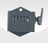
5. Adding a mechanical rotary counter to the spindle motor wheel.
6. Switches for rec/play, drive I/O, motor I/O, direction etc.
7. Building it all into a casing.
Maybe even start a production! :D
by mcanulty » Sat Oct 08, 2011 08:26 UTC
Glad to post it, I am getting a kick out of the idea of changing the front page a bit more often, and it's great to have enthusiastic people posting new work.
I love the idea of a mechanical counter for spindle rotations, that sounds very satisfying, although expensive! :) I would be psyched to support your work on a product and provide a place with oml to help you to get it out there, I've been learning a lot about product design from my work with Keith McMillen lately, and I feel like the ultimate end goal of it all is to be able to help others learn similar things, so that we can all contribute our ideas and excitement to the greater good. Plus I've been stalled in my work with floppies as I have been sidetracked with other things, so if you are psyched to make a stab at it, it will get me psyched again to start getting things together.
Regarding speed, I wonder about whether or not you are right, if maybe there could be a place in 3.5 inch drives to put a pot, just like in the 5.25 inch drives. It is definitely worth investigating. If you can post the info on the drives you are looking at, I'll look through my drives and see if I have something similar, it would be interesting to be looking at the same hardware with someone. They all seem so different. When I was at maker faire with this project, I met this guy who seemed to have first hand knowledge of so much of this drive lore, and then Jeri Ellsworth walked by and said hi (which was very exciting), and someone else was there trying to talk to me, and I quickly wrote down the man's info on a piece of paper and haven't been able to find it. A bit of bad luck there, he was fascinating and deeply knowledgeable. Jeri's main comment was that so many people have asked her to put out a board that there was definite interest and that I should get a board out for people. And then all this time has passed and I haven't yet done so. Well, I didn't know the first thing about designing a pcb at the time, but now that I do (how fast time flies and knowledge multiplies!) it all seems like it would be so simple if I could just put in the time. So if you're interested, maybe we could start drawing up and sharing schematics of workable circuits and then pick and choose from them and lay out a board. I've got a few things already drawn up and just need a bit of a push to get them to be usable in first rev form.
So anyway, if you've got enthusiasm, I've got knowledge! If you're still in the midst of it all, we can compile our knowledge together and get something permanent made before you finish and move on to other projects! :) Outside of the forum you can mail me at mcanulty [at] openmusiclabs.com. But posting as much as possible on the forums is very valuable, people do find the post and learn from them.
by Paleorama » Sat Oct 08, 2011 15:58 UTC
It's good to see that the enthusiasm "infects" (guess it's common in danish everyday-speech) and I know how it can feel when once you took the time and learned the basics of a project and went off a side track, then someone sees your project layout/prototype after some time and starts getting these rushs of creative ideas and new takes on the subject. It can only be mutually inspiring!
And that's why I love your forums here, it lets people follow the progress amongst the other users and thereby taking it step by step themselves. I've been looking at this project for 2 years now and I just couldn't figure out what it all meant. And Jeri's video was just a mystery (as the girl, I guess ;)). I'm being told that I'm good at explaining things in an easy and understandable manner, but I think the main issue on this project is, as you rightly mentions yourself, that there's a lot of different drives out there. The IDE cable is fairly common wiring, the heads is a little bit more trial and error, the pin for spindle motor speed is all up to the floppy controller IC - it must be. But we'll see soon.
So I'm all new in this branch of hardware hacking. But it's like the light is suddenly turned on when you get it working and now I feel like I could make these everyday :D
As goes for the mechanical counter, I ripped it out of an old dictaphone (casette tape, that is) when trying to wire up the heads and got the idea as sent from above :) And I have good sources of cheap electronics around the web and my town here in Denmark. It shouldn't be any head ache.
As for these days, I've got time as the only thing in the world. (Which leads people to build a sound recorder of an old floppy drive, I guess :D)
I'll contact you on your mail and we'll se if we can work something out :)
Best regards,
Daniel / Paleorama
by Paleorama » Sat Oct 08, 2011 16:07 UTC
And for the ultrasonic sound to erase the disk, I wanted to build some simple circuit, based on 555/556 timers and came across this schematic on a dog-repellent project.
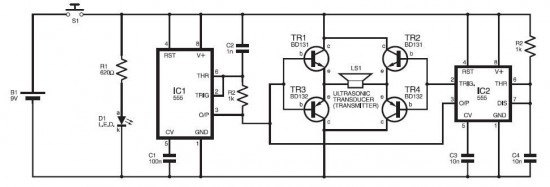
The ultrasonic dog repellant uses a standard 555 timer IC1 set up as an oscillator using a single RC network to give a 40 kHz square wave with equal mark/space ratio. This frequency is above the hearing threshold for humans...
Link here:
http://electroschematics.com/1026/dog-r ... t-circuit/by mcanulty » Sun Oct 09, 2011 02:45 UTC
Yeah, you could probably get rid of all those transistors if you wanted to and replace them with an lm386 if that would be more comfortable, and you should only need one 555 I think, although I am not very skilled in their use so I'm not sure why they wanted two here. You could also use an arduino to generate a 40khz squarewave and knock the edges off of it with an rc filter. I used a phase shift oscillator, which might have been overkill.
Here's the page from my notebook with the bias schematic drawing I made at the time, which hopefully is not more confusing than it is helpful.
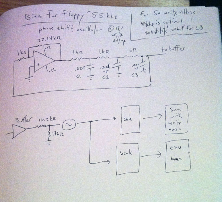
These days I would probably set up the arduino or the 555 to generate a square wave and then filter it into a sine wave. The issue I remember with the phase shift oscillator was that it sometimes didn't want to get going and I had to give it a kickstart with my finger or by yanking the feedback resistor and putting it back in. But it did make a very beautiful sinewave. One thing to watch out for that I forgot about is that when you are summing the bias and the audio, you want to avoid clipping in the final output stage, so remember to leave room to scale them. I buffered the bias and then stuck a pot after the buffer so I could dial in the right scaling while developing.
by mcanulty » Sun Oct 09, 2011 02:50 UTC
Those two resistors after the buffer stage are a scaling stage, I can't remember why I wrote down that I was putting it through another scaling stage immediately afterwards, it might be because I was actually amplifying the bias when I was erasing, and then just adding it when I was writing audio, so I split them into two stages.
by Paleorama » Mon Oct 17, 2011 03:48 UTC
Thanks for the blueprints! I'll look deeper into your schematic when I get to that part - I'm still doing the research on the spindle motor and I think I've got jackpot!
This link provides us with pretty much everything we need to know!
http://sturntech.com/blog/2010/12/04/reverseengineering-fd1231h-floppy-disk-spindlemotor-controller
..of course, no two drives are completely identical - he used a NEC FD1231h 3.5" FDD.
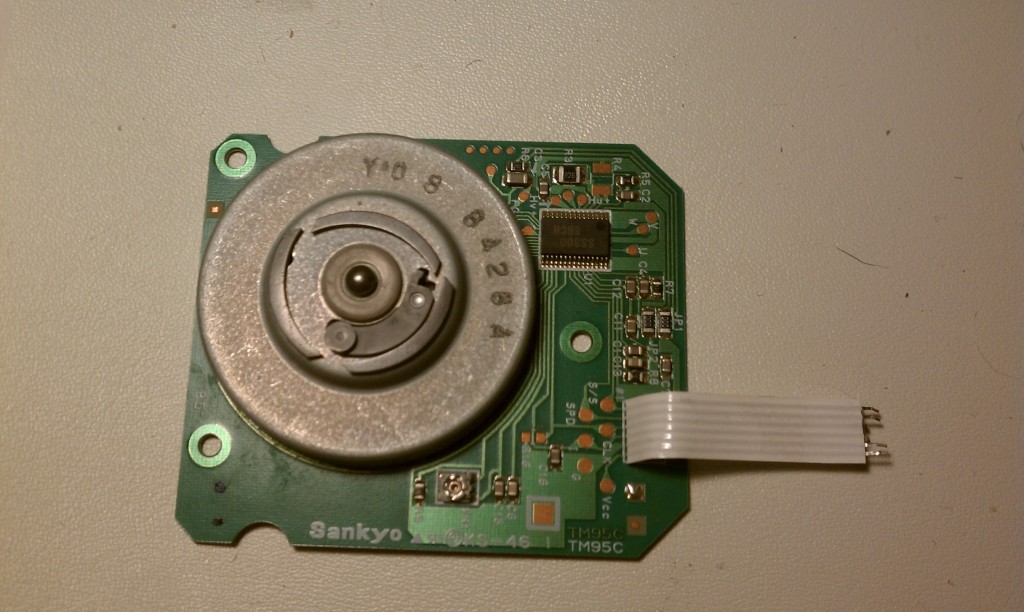
But he provides us with a very nice detailed explanation of the wires going to the spindle motor PCB and some datasheets for deciphering the IC.
by mcanulty » Mon Oct 17, 2011 05:44 UTC
Woah, good find!
by Paleorama » Thu Oct 20, 2011 22:31 UTC
Yeah, it's definately just what I was looking for! Very thorough explanation of how to control the motor.
Looks like it's not possible to speed up the rpm more than the 360 rpm, but possible to slow it down to the roughly 120 rpm (according to the experiments from the guy with the drawbot)
This guy, with the guide just provided, says the following:
The CLK signal I arbitrarily decided to generate a 300kHz 50% duty cycle square wave (since this frequency was used by one of the reference Motor Control ICs I found earlier). For the CLK signal, I used a 555 timer circuit. When interfacing the 555 output to the CLK signal line, I used a BC547 NPN transistor.
A CLK of 300kHz resulted in a pretty jerky spin motion. Reducing the frequency worsened the performance. Increasing the frequency helped a lot, with a smooth continuous rotation discovered around 1MHz. Further increases in frequency heated the motor driver IC up quite a bit, without any noticeable gain in spin performance.
Using a 1MHz CLK signal, I was able to get this motor to spin at near 360RPM (measured with light strobe).
But it could still be very interesting to record audio at a lower rpm, and playing with the clock frequency as a pitch knob - and have different rpm's during recording. Could be very interesting for audio-collage. I hope I can get this pulled - will try tomorrow night when the wife is off to town. ;)
by Paleorama » Fri Oct 21, 2011 02:34 UTC
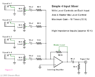
I'm drawing a complete diagram of how I want to build this bastard, I got to the stage of the signal bias and read your post and illustration - thanks a lot BTW! - I'm not sure I really get the drawing you've made but I think the main issue would be summing the signals without some weird impedance-loss and all this bizzare stuff that I'm not that educated on yet, but I think my conclusions for my build is:
RLC oscillator for the bias! (easy to build and pretty neat for producing a fixed sine wave signal)
OMP-AMP for summing the signals (as it's inverting the phase, afaik)
wadd'ya say?
EDIT:
Okay, seems like it'll be no problem as I'm already planning on driving my input to the FDD heads through a OP-AMP circuit, and as far as I can tell, it just requires a few resistors between the bias signal and the OP-AMP input!
by zool » Mon Apr 09, 2012 22:22 UTC
the way i went about adjusting the brushless motor was to probe around with a potentiometer, usually on a capacitor or resistor close to the speed control chip and tied to ground
(not all drives are going to be the same)
it will change the speed of the motor from 0~150rpm i think and you can add a switch to go back to 300rpm if you want
at low rpms the motor is a little jerky and the sound is not smooth either.
i would be interested if you could slow the motor down so that it has a very low rpm yet still runs smooth, i'm not sure if it's even possible with the type of brushless motors in floppy drives
by Paleorama » Sat May 12, 2012 03:56 UTC
Oh yeah, I could imagine the motor running yerky with a low frequency in the pulses. Still interested to do it though!
by Paleorama » Wed Oct 03, 2012 23:54 UTC
Update:
I now managed to adjust the motor speed by following the guide i provided at page 1 (bottom), I simply cut the SPD wire, and scaled the drive voltage with a pot. It adjusts the speed to what I think is nearly 50% but there's a steep drop all of a sudden from high to low speed. Any suggestions what I might be able to do? I tried several potentiometers, all from 1K to 1M. Same.
by Paleorama » Mon Oct 15, 2012 01:53 UTC
I figured out how to fix the sudden speed change to a nice and smooth speed change. I sent out a PWM pulse from my dear arduino and changed it into a analog out with an RC-circuit. Video will be up soon!
by guest » Mon Oct 15, 2012 21:32 UTC
what value R and C did you use?
what is the PWM frequency? a higher PWM frequency may not require the filter.
by Paleorama » Tue Oct 16, 2012 15:47 UTC
guest wrote:what value R and C did you use?
what is the PWM frequency? a higher PWM frequency may not require the filter.
Acutally a filter may not be required at all but then there will be no need for PWM either. The SPD pin on the spindle PCB takes float voltage, the CLK can be sent a ~1MHZ signal to drive the spindle motor.
The thing is, I tried with just taking a pot and scaling a current between 0 and 5V, directly to the SPD pin and there was this (as before mentioned) very steep transition between the highest and lowest speed on the middle position of the pot. I tried converting the PWM signal to "analog out" with the RC filter and now it works smoothly.
(I used the values 4,7K res. and a capacitor of 1uF.)
Oh yeah and the pulse freq is determined by a potentiometer to Analog In on the AVR. Just scaling between 0 and 1023.
by Bendu » Sat Jan 18, 2014 18:13 UTC
EDIT:
I just realized my oversight … this would only apply to old-school belt drive floppy drives.
http://m.youtube.com/watch?v=vi_oE3ayn0 ... i_oE3ayn0M
Extrapolating from Dr. Breen:
I get the appeal of an electrical solution for its possible more finite control but...
How about an inelegant but simple mechanical solution to control motor speed?
A larger spindle on the motor.
You could also place an tension arm with a roller on it and vary its distance from the spindle to vary the speed.
A smaller spindle would increase the speed like it shows in Dr. Breen's video when the belt snaps down below the upper spindle.
Personally I also like the idea of an exposed spindle to enable scratching.
b