Tools and Techniques for Musicians, Composers, and Tinkerers
How to control the motor
22 posts · 54001 views
by aelginfluensa » Mon May 30, 2011 10:57 UTC
Hi
I started looking into this project again, but I haven't come very far..
What I am thinking of now is how to control the motor (without Arduino). I have found a map over the pins here:
http://www.interfacebus.com/PC_Floppy_Drive_PinOut.html. But how to talk to them? To make them go low, you connect them to ground?
Could you please give some advice on how to connect the pins! It is hard to see how you have done it on the videos..
Many thanks!
by aelginfluensa » Mon May 30, 2011 23:49 UTC
Allright, I did some haxing on my own.. with the help of
http://www.codeproject.com/KB/system/floppystepper.aspx, who only used the step motor of the floppy.
I connected pin 14 to ground (with a thin cable) to select Drive A. Then if I connected pin 20 to ground the heads moved one hack forward, and moved again when I removed the pin. If I connected pin 18 to ground the heads moved backwards instead.
by Paleorama » Wed Sep 28, 2011 13:15 UTC
Hi Aelginfluensa,
How far did you get with the project?
pin 14 is for connecting drive 0, that's right
pin 18 is for direction and 20 requires a pulse in (anyone knows if it can be driven by a 555 timer?)
pin 10 is for turning on the spindle motor, it needs to be on to write to the current track.
at first I thought the write enable pin (24) had to be LOW to write audio to the disk but that wasn't at all required.
in fact, I wasn't able to turn on the motor if the write enable was on.
by mcanulty » Sun Oct 02, 2011 00:28 UTC
Thanks Peleorama, yes, I believe it can be driven by a 555, I eventually used an arduino to pick up the pulses and then I used them for timing and made my own pulses with the arduino digital pins. If you're using a 555, just be sure to to keep the signal voltage at 5v, you don't want to give too high a voltage to the digital inputs on the floppy drive.
by Paleorama » Wed Oct 05, 2011 16:18 UTC
Thanks, I'll keep that in mind. I'll soon be building 555-timers and OP-amps for in/out-put signals.
I'll post the schematics here if I get it working. Already found a nice OP-amp IC that is driven by 5V.
Do you know what frequency the arduino PWM pulse is in the default stepper-sketch that is included in the arduino app?
I couldn't find any indications anywhere and I'm not so sharp at programming. :)
by mcanulty » Sat Oct 08, 2011 08:37 UTC
Off-hand I don't, but I encourage you to open up the avr atmega328 data sheet and set the pwm rate to whatever you want. It seems a bit scary, but it's very simple and it's empowering to realize that you can set things the way you want them to be. I just open up a notebook and I walk through it bit by bit. 'this bit needs to be set, this bit needs to be zero, this bit needs to be...etc.' And then once that's done, I start to program it in and I see what happens.
Although, for drive signals, you might have good luck just flipping a bit, calling a delay function, and then flipping it again. For motor control pwm might be useful, but not for stepper motors, only for current driven motors. Anyway, this is probably my lack of knowledge about the stepper program speaking, if you direct me to a specific setup and pinout I can try to apply myself more specifically and see if I can be of better assistance.
by mcanulty » Sat Oct 08, 2011 08:41 UTC
I took a programming class once, a long time ago, when I was a freshman undergraduate, and I didn't learn a lot of useful stuff, but I remember the exams were on paper, we had to write down programs on paper. I think of that sometimes when writing in my notebook. If it compiles right on the page, it should have a good chance on the phosphor! or lcd or led or whatever it is now :)
by mcanulty » Sat Oct 08, 2011 08:45 UTC
If you have trouble with the op amps, let us know, user guest has enormous op amp knowledge and will probably be able to write up helpful posts with regards to that which may result in something good that can be put up on the main site as well. Working with the floppy audio project was how I learned not to be afraid of them and to gradually get a feeling for them. They're not so scary, in fact they're designed to take the scariness out of analog electronics. Op amps are our friends! :)
by kris_mcdougall » Thu Oct 13, 2011 00:59 UTC
Hey guys. I really admire your work. I'm hoping to get three or four of these drives wire together and then build a patch to control them in Pd. For now, though, I'm having trouble getting the stepping motor to do it's thing.
I grounded pin 16 to get the motor to run (pin 10 didn't do anything, even with pins 10 and 14 grounded to "select A/0... I guess this Samsung drive thinks it's a 'B/1'?) Also strange, grounding it to any of the odd-numbered pins on the connector did nothing; I had to go solder a ground to the Molex connector. But the motor spins just by connecting pin 16 to ground.
Grounding pin 12 lights up the front LED for some reason, even with no diskette in the drive... this is the pin I have to ground to select drive "B/1" right? Joining pins 8 (index pulse) and 20 (step pulse) does nothing. The only way I've gotten the stepper motor to move at all is by grounding both 12 (select 1/B) and 20 (step pulse) simultaneously. This causes the stepper motor to start stepping back and forth rapidly, even once contact is broken. This doesn't stop until I either turn on the motor or eject the disk.
I'm really puzzled. Any suggestions?
by mcanulty » Thu Oct 13, 2011 07:06 UTC
Hey Kris! Can you post a picture or drawing of the port you're looking at? Then maybe we can start drawing in labels and connections and things like that and see if we can make sense of things.
by kris_mcdougall » Thu Oct 13, 2011 15:46 UTC
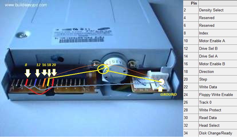
Here's a doodle of what I was trying to describe. This is actually exactly the same drive that I have. The reason that many of the pins don't act as grounds is that they are missing from the connector on the drive! So, as I was explaining, but more concise:
EDIT: Got it to work! Strangely... it's wired exactly how I had it before, I just ripped it all off and started over. I built myself a system of switches not unlike the ones Jeri showed in her video:
- My drive is wired up as a "B" drive, so I soldered pin 12 (select B) permanently to ground,
- I have a simple on/off switch from pin 16 (motor enable B) to ground to turn on the motor,
- Pin 18 (direction) is also wired to ground via an on/off switch,
- And to step, I've wired a moment switch that joins pins 8 (index pulse) and 20 (step pulse). It steps once per revolution with the switch depressed and maintains the same position when it is not.
The direction on the stepper motor seems to have a mind of its own on this drive. Sometimes it will function perfectly, other times it will stop halfway towards the center and start stepping backwards. And on another drive, it sometimes works correctly, but most of the time it will step twice in rapid succession every two revolutions. Weird.
by guest » Sat Oct 15, 2011 04:13 UTC
perhaps the switches gave a better connection
just touching a wire
can actually cause many little contacts to occur
each one sending a pulse to the controller
by mcanulty » Sat Oct 15, 2011 04:20 UTC
Sounds like your work bench may be haunted!
I agree with what guest said, those better connections are probably to thank for it. And with regards to the direction pin, are you giving it a clear signal of power or ground when you want to change direction? It sounds a little like it may be floating so that random movements of electrons in the air are causing it to change direction. That would be my first guess, but a haunting is a close second :)
by Paleorama » Sun Sep 30, 2012 23:35 UTC
mcanulty wrote:If you have trouble with the op amps, let us know, user guest has enormous op amp knowledge and will probably be able to write up helpful posts with regards to that which may result in something good that can be put up on the main site as well. Working with the floppy audio project was how I learned not to be afraid of them and to gradually get a feeling for them. They're not so scary, in fact they're designed to take the scariness out of analog electronics. Op amps are our friends! :)
Fall is here and I've been preparing another poor floppy drive for sweet audio experimentation. Right now, the heads are hooked up to a tape player in an old radio, in which I just desoldered the tape heads. The amplification is very low so I thought it might be time to hear what dear
guest has to say about the op amp matters. Would a standard LM386o or TL072 be appropriate? A gain of what? 10/50/100 times? I am curious (and keen to build!)
by guest » Mon Oct 01, 2012 06:15 UTC
you will want a really low noise, and high badnwdith opamp for this. a typical design is shown here:
http://www.analog.com/static/imported-f ... 3AN106.pdf
check out figure 21. its a non-inverting amplifier with a bass-boost. the high bandwidth and low noise are required because you will need a gain of 500 or so. they show the op-37, which has a 63MHz bandwidth and 3nV noise. its a bit expensive, but not too bad. you can try other amps like the TLC071, which is 50MHz and 7nV, and half the price.
by Paleorama » Mon Oct 01, 2012 16:31 UTC
Interesting, thanks a lot! of course one prefers low noise op amps when dealing with these extreme gaining powers. Does this go for both input and output signal, and another thing: is it true that there's no way to both record to the disk and play back the signal at the same time? I tried using two of the head pins for record while playing back and it resulted in the audio supposed to be recorded was fed into the amplifier (very loud)
by guest » Mon Oct 01, 2012 20:03 UTC
i dont think the heads are shielded from one another, like they are in a reel-to-reel machine, although i cant say for sure. but i would guess that it isnt possible, as there arent seperate tracks, there is only 1 data track. the record signal amplifier doesnt need to be low noise. a high output current output amplifier might be able to write directly, without transistor buffers. the TLC071 can do 100mA, so it might be able to do it.
by Paleorama » Tue Oct 02, 2012 21:42 UTC
guest wrote: a high output current output amplifier might be able to write directly, without transistor buffers. the TLC071 can do 100mA, so it might be able to do it.
Can you specify what you mean by this? I am curious. :) Write directly?
by guest » Wed Oct 03, 2012 03:19 UTC
i mean that you could connect the output of the opamp straight to the write head. the write heads are very low resistance, so they draw a lot of current. some opamps are better at sourcing a lot of current without distorting or saturating.
by Paleorama » Wed Oct 03, 2012 14:55 UTC
and by write head, do you mean the wire I soldered to the ribbon cable heads or the write data port on the control pin? I am confused because if you mean the heads, then I would still get audio out from the amp playing back the from the heads...
by guest » Wed Oct 03, 2012 22:03 UTC
yes, to the read/write head. this does mean that the read circuit will get a signal from the write amplifier when it is activated. so there will need to be some gating circuit that shuts off, or disconnects one of them.
by Paleorama » Wed Oct 03, 2012 23:44 UTC
guest wrote:yes, to the read/write head. this does mean that the read circuit will get a signal from the write amplifier when it is activated. so there will need to be some gating circuit that shuts off, or disconnects one of them.
See that's my problem: it could be nice to record onto the disk while listening, so the audio doesn't have to be shut off. Anywho, it'll work just fine if not. :)